Superheterodyne Receiver
A superheterodyne receiver uses signal mixing to convert the input radio signal into a steady intermediate frequency (IF) that can be worked with more easily than the original radio signal that has a different frequency, depending on the broadcasting station. The IF(MF) signal is then amplified by a strip of IF(MF) amplifiers and then fed into a detector that outputs the audio signal into an audio amplifier (LF) that powers the speaker. On this page, we will learn about the working of a Superheterodyne AM receiver with the help of a block diagram and the instructions to build your own reciever (HX108-2). Most AM receivers found today are of superheterodyne type because they allow for the use of high selectivity filters in their Intermediate Frequency (IF) stages and they have high sensitivity (internal ferrite rod antennas can be used) due to the filters in the IF(MF) stage which helps them in getting rid of unwanted RF signals. Also, the IF(MF) amplifier strip providing high gain, good strong signal response because of the use of automatic gain control in amplifiers and ease of operation.
HX108-2 AM Receiver
Most of me inspiration to build and analyse the HX108-2 superheterodyne AM MW radio receiver kit is based on the website from Paul Gallagher all credits go to him for sharing his explanation on his webpage LEAP. (Little Electronica Art Projects)
AM/MW radios are of very little use these days in Europe. There is no local AM broadcasting, just a few stations from foreign
country's that can be picked up if you’re lucky. However, there’s still a great deal that can be learned from studying simple AM superheterodyne circuits. Although it’s possible to build the entire kit in under an hour, I decided to carefully follow up Paul's approach and build the kit sub-system by sub-system, build up from audio out to RF in.
The Radio Mechanic: an excellent desktop freeform build of the HX108-2 circuit
The Kit HX108-2
I purchased my HX108-2 kit from seller on aliexpress.
It was generally OK, with no missing parts.
The basic specification for the kit:
- Frequency Range: 525-1605kHz
- Intermediate Frequency: 465kHz
- Output Power: 100mW
- Power Supply: 3V, 2xAA
- Speaker: 57mm diameter 8 Ω
.jpg/picture-200?_=17f09239496)
Transistors
The transistors are classified by ß(hFE), and it seems many kits substitute different parts of similar capability:
9018G ß = 80-100
9018H ß = 97-146
9013H ß = 144-202
Audio Transformers (LF)
There are two audio transformers used in the final stage:
B6 input audio transformer (蓝 blue or 绿 green)
B7 output audio transformer (黄 yellow or 红 red)
I received a 绿 green and 黄 yellow in my kit. For reference, I measured the resistance of each coil:
绿 green: 220Ω : 104Ω + 104Ω
黄 yellow: 2.5Ω : 6Ω + 6Ω
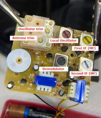
IF Transformers (MF)
There are four transformer cans used in the design:
B2 红 red: local Oscillator & Mixer
B3 黄 yellow: first IF (MF)
B4 白 white: second IF (MF)
B5 黑 black: Demodulator
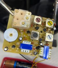
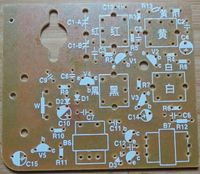
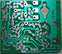
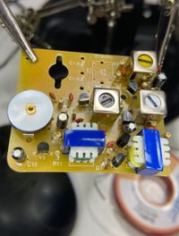
PCB Circuit Board
Circuit Design
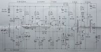
The HX6B is aSuperheterodyne Receiver design with two IF(MF) stages. The circuit basically maps to the following stages:
- RF Filter: B1, C1a antenna tuner
- RF Amp: V1
- Local Oscillator and Mixer: B2, C1b
- First IF(MF) Filter and Amp: B3, V2
- Second IF(MF) Filter and Amp: B4, V3
- Demodulator: B5, V4 (Detector)
- Audio Amp: V5 audio driver/preamplifier
- B6, B7, V6, V7 push-pull class B power amplifier
.jpg/picture-200?_=17f07c6cb18)
As you can see the block diagram has 11 different stages, each stage has a specific function which is explained below
RF Filter: The first block is the ferrite rod antenna coil and variable capacitor combo, that serves two purposes - RF is induced into the coil and the parallel capacitor controls the resonant frequency of it, as ferrite antennas receive the best when the resonant frequency of the coil and capacitor is equal to the station's carrier frequency – this way it acts as an input filter of the receiver.
Heterodyne Local Oscillator: The second block is the heterodyne, also known as the local oscillator (LO). The frequency of the local oscillator is set, so either the sum or the difference of the RF signal’s frequency and the LO’s frequency is equal to the IF (MF) used in the receiver (usually around 455 kHz).
Mixer: The third block is the mixer, the RF signal and the LO signal is fed to the mixer to produce the desired IF (MF). Mixers found in common AM receivers output the sum, the difference of the LO and RF’s frequencies and the LO and RF signals themselves. Most often in simple transistor radios, the heterodyne and the mixer are made using one transistor. In higher-quality receivers and those that use dedicated integrated circuits, such as the TCA440, these stages are separate, allowing for more sensitive reception due to the mixer outputting only the sum and difference frequencies. In one transistor LO-mixers, the transistor operates as a common-base Armstrong oscillator and the RF taken from a coil wound on the ferrite rod, separate from the resonant circuit’s coil, is fed to the base. At frequencies different from the resonant frequency of the antenna resonant circuit, it presents low impedance, so the base stays grounded for the LO signal but not for the input signal, due to the antenna circuit being of parallel resonant type (low impedance at frequencies different from resonance, almost infinite impedance at the resonant frequency).
First IF (MF) Filter: The fourth block is the first IF(MF) filter. In most AM receivers, it is a resonant circuit placed in the collector of the mixer transistor with the resonant frequency equal to the IF(MF) frequency. Its purpose is to filter off all signals with a frequency different from the IF(MF) frequency because those signals are unwanted mixing products and don’t carry the audio signal of the station we want to listen to.
First IF (MF) Amplifier: The fifth block is the first IF (MF) amplifier. Gains of 50 to 100 in each IF (MF) stages are common if the gain is too high, distortion can take place, and if the gain is too high, IF (MF) filters are too close to each other and not properly shielded, parasitic oscillation can take place. The amplifier is controlled by AGC (Automatic Gain Control) voltage from the demodulator. AGC lowers the gain of the stage, causing the output signal to be roughly the same, regardless of the input signal amplitude. In transistor AM receivers, the AGC signal is most often fed to the base and has a negative voltage – in NPN transistors pulling the base bias voltage lower, reduces gain.
Second IF (MF) Filter: The sixth block is the second IF filter, just like the first one it is a resonant circuit placed in the collector of the transistor. It only lets signals of the IF(MF) frequency – improving selectivity.
Second IF (MF) Amplifier: The seventh block is the second IF(MF) amplifier, it is practically the same as the first IF(MF) amp except it is not controlled by AGC, as having too many AGC controlled stages, increases distortion.
Third IF (MF) Filter: The eighth block is the third IF(MF) filter, just like the first and the second one is a resonant circuit placed in the collector of the transistor. It only lets signals of the IF(MF) frequency – improving selectivity. It feeds the IF(MF) signal to the detector.
Detector: The ninth block is the detector, usually in the form of a germanium diode or a diode-connected transistor. It demodulates AM by rectifying the IF(MF). On its output, there is a strong IF(MF) ripple component that is filtered out by a resistor-capacitor low pass filter, so only AF component remains, it is fed to the audio amp. The audio signal is further filtered to provide the AGC voltage, like in a regular DC power supply.
Audio Amplifier (LF): The tenth block is the audio amplifier; it amplifies the audio signal and passes it onto the speaker. Between the detector and the audio amplifier, a volume control potentiometer is used.
Speaker: The last block is the speaker (usually 8 ohms, 0.5W) that outputs audio to the user. The speaker is sometimes connected to the audio amplifier through a headphone jack that disconnects the speaker when headphones are plugged in.
Step 1: Power
Can’t achieve much without power!
There are actually two “power rails” in the circuit: the full power of the battery is used to drive the audio amplifier and a ~1.4V rail is established using 2x diode drops to power the RF stages
Ref Item Installed
D1 1N4148
D2 1N4148
R12 220Ω
C15 100µF electrolytic
W switch and 5kΩ pot
.jpg/picture-200?_=17f091d7d5f)
Step 2: Speaker and Battery
Mounting the speaker and battery clip in the housing. Speaker is connected to the PCB, however I’ve left power disconnected for now as I’ll use a bench power supply for testing so I can read off total current and voltage.
Ref Item Installed
Y 8Ω speaker
.jpg/picture-200?_=17f093a57cd)
Step 3: Audio
This step adds the audio pre-amp and power amplification stages, starting from C8/R9, C11 is mislabeled as C6 on the schematic.
Ref Item Installed
R9 680Ω
R10 51kΩ
R11 1kΩ
C8 22nF (223)
C9 22nF (223)
C10 4.7µF electrolytic
C11 22nF (223)
C12 22nF (223)
C14 100µF electrolytic
B6 input audio transformer (蓝 blue, 绿 green) 绿
B7 output audio transformer (黄 yellow, 红 red) 黄
D3 1N4148
V5 9013H
V6 9013H
V7 9013H
.jpg/picture-200?_=17f326cd0d9)
Step 4: Demodulator
The V4 transistor is being used as a detector in this stage.
Ref Item Installed
R4 20kΩ
R8 1kΩ
C4 4.7µF electrolytic
C7 22nF (233)
B5 transformer 黑 black
V4 9018H

Step 5: Second IF Stage
Ref Item Installed
R6 62kΩ
R7 51Ω
C6 22nF (223)
B4 transformer 白 white
V3 9018H

Step 6: First IF Stage
Ref Item Installed
R3 100Ω
R5 150Ω
C5 22nF (233)
B3 transformer 黄 yellow
V2 9018H
Step 7: RF Front-end
All the remaining parts:
Ref Item Installed
R1 100kΩ
R2 2kΩ
R13 24kΩ
C1 CBM230p var cap
C2 22nF (233)
C3 10nF (103)
C13 22nF (103)
B1 antenna BS x 13 x 55
B2 transformer 红 red
V1 9018G

Step 8: Final Tuning and Testing
The main thing I needed to do was adjust the oscillator so that the frequency range roughly lines up with the decal/front dial.
I got “close enough for now” by just adjusting B2 红 red:
set the variable capacitor to position the front dial at the expected frequency of the signal I was aiming for adjust B2 红 red until the signal is received at best strength/quality
Shango066 has a great video on tuning the HX108-2.

AM RX
Superhydrodyne
HX108-2 AM Receiver
.jpg/picture-200?_=17f091d8054)