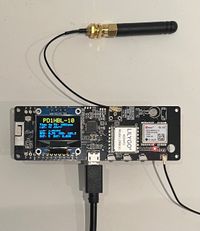
LilyGO TTGO T-Beam - LoRa 433MHz - NEO-M8N GPS - ERP32
Product Features
ESP32
Lastest ESP32 Version: REV1
WIFI
Bluetooth
8MB PSRAM
4MB Flash
3D Antenna
LORA
Product Description
Working voltage: 1.8~3.7v
Acceptable current:10~14mA
Transmit current: 120mA@+20dBm
90mA@+17dBm
29mA@+13dBm
Operating frequency: 433/470MHz(433HMz version) /868M/915M(868MHz version)
Transmit power: +20dBm
Receive sensitivity :-139dBm@LoRa &62.5Khz&SF=12&146bps
-136dBm@LoRa &125Khz&SF=12&293bps
-118dBm@LoRa &125Khz&SF=6&9380bps
-123dBm@FSK&5Khz&1.2Kbps
Frequency error:+/-15KHz
FIFO space : 64Byte
Data rate :1.2K~300Kbps@FSK
0.018K~37.5Kbps@LoRa
Modulation Mode :FSK,GFSK,MSK,GMSK,LoRa TM,OOK
Interface form : SPI
Sleep current :0.2uA@SLEEP
1.5uA@IDLE
Operating temperature :-40℃- +85℃
Digital RSSI function
Automatic frequency correction
Automatic gain control
Low voltage detection and temperature sensor
Fast wake-up and frequency hopping
Highly configurable data packet handler
GPS
GPS modules NEO-6M, 3V-5V power supply Universal
Destined module with ceramic antenna, signal super
Save the configuration parameter data EEPROM Down
With data backup battery
There are LED signal indicator
Default Baud Rate: 9600
Power
Power Supply Input USB 5V/1A
Charging current 500mA
Battery Input 3.7-4.2V
Charge IC AXP192
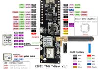
Pin Schematic
LoRa APRS Trackers
hello, wireless enthusiasts here is the channel with the strange swiss distortion in the signal with a new episode around wireless and other exciting stuff make sure you subscribe. If you do not want to miss the following emissions in this video, we will cover the basics of aprs, as well as lora, build a lora aprs tracker build a lora aprs. I gate, which also can be configured as a digipeater, see how we can display positions of trackers. The automatic packet reporting system. Short aprs was invented in the 1980s by bob runinga and is also used today to transmit position reports via handbands in europe. We use 144.8 megahertz and in the us they use 144.’. I do not know where standard aprs networks on 70 centimeters are operational. The aprs system consists of the following parts: trackers digipeaters eye gates, the aprs network and sites that store and display the positions. The origin of a message is the tracker: it transmits its message via air to either an eye gate or a digipeater. The digipeater retransmits messages till it hopefully reaches an eye gate or its destination. The igates transfer the message via the internet into the aprs network and finally, it arrives at places like aprs.fi, where it is stored and displayed. Only one frequency is used for all messages. That is why digipeater should not re transmit messages endlessly, as we will later see. The path determines how often a message will be: retransmitted modern, vhf handhelds, like the any tone 878 have a gps built in and automatically transmit your position.
If you want, you also get special tracker hardware for the purpose, but unfortunately it is not cheap. These trackers have at least one watt output and consume quite some power. Trackers are also used for balloon tracking by the way, a few years ago, same tech invented and patented a new transmission protocol for low power iot devices. They called it lora long range and low power to reach this goal. They reduced the transmission speed. Why were they able to patent it low speed frequency shift? Keying systems are known forever because it is pretty different from fsk modulation. Its bandwidth is 125 kilohertz and not only 10 kilohertz of regular fsk aprs. Usually we reduce the bandwidth to get better sensitivity, not here they can get much more sensitivity, particularly with low data rates. With this big bandwidth, keep in mind, 10 db, more sensitivity at least doubles the range instead of two constant frequencies. They use a chirp signal which changes its frequency for each bit and makes it less prone to frequency in accuracies. This is an advantage because you can work with cheaper quartz crystals and for satellites it can handle the doppler effect quite well. This is why many newer cubesats use this protocol. Instead of fsk lora uses the concept of spreading factors. Sf7 is fast and therefore has less range. Sf12 is the slowest mode with the best range spreading means that the information is spread throughout the transmission to get redundancy? A short disturbance cannot harm the signal.
Lora aprs uses sf12, which has the disadvantage. That one message is long and blocks the frequency for some time, but its range is excellent. Do you want proofs for this enormous range? A few years ago i was able to breach kilometers with a seven centimeter long antenna and a few milliwatts, and i regularly get signals from lora satellites over two thousand kilometers. You find the world record video on my primary channel and a video on how to build such a satellite ground station on this channel for the satellite ground station. I use a diy ground plane and the same cheap receiver board. We will use for our eye gate. Fortunately, 433 megahertz is also an ism band and therefore we get lora modules for these frequencies and because this technology is made for cheap iot devices, we get complete boards with an mpu, a display, a gps, a battery holder, wi fi, bluetooth and lora for 35 dollars. Delivered at our doorstep, the board is called t beam. In addition, we can print a cued case and ready is our tracker hardware. Now we just need the software. Fortunately, peter 0e5 bpa took over an idea from some fellow hams in vienna and developed a open source project for somebody experienced with arduino microcontrollers and platform io. It should be possible to customize and install it in a few minutes. You find a quick start guide on the project page and therefore i will not show how this is done.
Currently, the guide is only made for an eye gate. However, this is not a problem just download the files from the tracker repository. If you want to program your tbeam, the rest stays the same. However, i want to cover the configuration found in data tracker.json. You have to add your callsign with an additional number like hb9 bla 2. These extensions have a meaning and are standardized. For example, dash 7 is a handheld and dash 1 till dash 4 is a good choice for our lora trackers. The following parameter is the path default is wide one dash one, which means that if a digipeater receives your packet, it transmits it if it hits a second digipeater, it is no more transmitted. This makes sure the network is not flooded with messages. So y1 1 is okay for the current lora aprs networks. The second number, by the way, is always one. Two other parameters can be changed: the symbol and the overlay. They determine how your tracker is presented on aprs.fi. Here you see the available symbols standard is the forward slash and the bracket, which leads to a runner symbol. The space shuttle would have used forward, slash and s. For example, the other parameters should be left if you want a tracker compatible with the existing networks. If you want to build your own network, you can change the frequency or the spreading factor. You can also reduce the output power, which is set to the maximum 100 milliwatt or 20 dbm.
Only in the rare case, you use an old version of the t beam. You have to change the environment to version 0.7. Next, you have to upload the code to your t. Beam using a usb cable, just hit this arrow and choose the correct com. Port. Do not forget to upload the configuration file by selecting it and hitting this command. Now your tracker is ready and displays your callsign. You should also see it on aprs.fi. If you have a laura, i gate in your vincinity. If not, you have to proceed to the next step, create your own eye, gate or digipeater. Also here we can use a prefabricated board because this board does not need a battery nor a gps. We have a wider choice. I use this lora32 board. You have to follow the same steps as with the tracker. Just with the different software. You can leave the board on default and again adapt the configuration this time there is more work to do. The file is called, is cfg.json and is also located in the data directory. Again, we have to add our call sign this time. A 10 extension is proposed. If we want to build an igate, we have to connect it to the internet and choose a static ip address or enable dhcp. I use dhcp and leave the rest on the default settings. Next are the wifi credentials and the message which will be displayed on aprs.fi. If you want to place your igate on the map, you have to enter its position by copying the coordinates from google maps using a keybeam.
We could enable the gps module by the way for igates. You must fill out the passcode field. It can be obtained from this home page just enter your call sign without number extension. This number is not a secret, but it is needed for i gates which transfer messages to the aprs network. I leave the aprs server, as is other regions, select the respective server and now it is an excellent time to look at the aprs network itself because it has to transfer thousands of messages every hour it uses load, balancing and a hierarchical structure. If you use one of these rotate addresses, you will automatically be connected to an available server, because the network does not store the messages. Other services like aprs.fi, aprsdirect.de or aprsmap.info, store and display them in a browser. You also get apps for your smartphones to access aprs.fi. It is also possible to transfer messages across aprs, but this is not supported by this project. Next is the digipeater and the beacon section. If you have no internet available for your device, you can configure it as a dg peter that transmits the messages over the air. This is an unmanned station and you have to check if your license allows to operate it. I never use the ftp or the syslog function, but i enabled mqtt and filled in the mqtt brokers address and credentials. Now i get all messages received by my igate as an mqtt message and i could use it to trigger an action.
I put my eye gate into one of these waste water pipes and added a 3d printed holder and a ground plane antenna, because i have other receivers on my roof. I connected it to the 5 volt supply of a close by device. Otherwise, you would have to add a power supply. The connection to the internet is made by wifi by the way you get also a small pcb. If you want to connect it directly to ethernet attila dl1 and ux compared standard with lora aprs, he found out that lora was more reliable. Despite 10 times less power and the smaller antenna and a last story. Andreas oe3dmb used this technology to track the position of his car via the q0100 geostationary satellite. With this short antenna and a 20 watt amplifier, the q0100 is 36 000 kilometers away by the way we deployed 10 eye gates around where i live, and german hams did. The same at the other side of the rhine river, so we are pretty much covered here. When do you start your project in your area? That is all for today. As always, you find the relevant links in the description 73 to everybody and please consider supporting the channel by using the links in the description.


.png/picture-200?_=185632510df)